
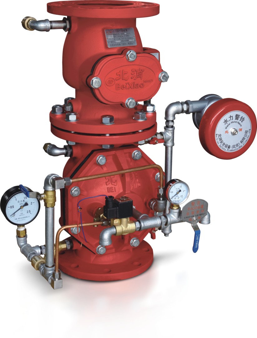
The preaction device is the main component of the preaction steam sprinkler system. It consists of a preaction alarm valve group, a control panel, a pneumatic pressure device and an air supply device. It is electrically, pneumatically, mechanically or otherwise opened to enable water to A one-way valve block device that simultaneously flows into the water spray system and simultaneously alarms. A 220V external power supply is required for both the control cabinet and the air supply unit. When the pre-action automatic sprinkler system is in the working state, the water distribution pipe is not filled with water after the pre-action alarm valve, and is filled with air with a pressure of 0.03-0.05 MPa to monitor the sealing of the pipe network. The adjustment of the electric contact pressure gauge for controlling the supply device is: 0.03 MPa lower and 0.05 MPa higher. When a fire occurs, the fire alarm automatic alarm system is connected or remotely controlled, and the pre-action alarm valve group is manually activated. The water distribution pipe is filled with water, and the end electric exhaust valve exhaust is converted into a wet automatic sprinkler system, and an alarm signal is issued at the same time. . When the fire is further developed, the sprinklers will start to sprinkler. Pre-action sprinkler systems are suitable for locations where water loss is a concern and where the ambient temperature is below 4 ° C or above 70 ° C.

Third, the working principle of the pre-action alarm valve
The rain alarm valve is the main component of the pre-action alarm valve group. The rain alarm valve has a water supply chamber, a system chamber and a control chamber. In the servo state, the pressure water in the control chamber pushes the diaphragm to seal the valve seat, separates the water supply chamber from the system chamber, and the rain alarm valve closes. When the solenoid valve is activated or manually started, the control chamber is relieved of pressure, and the pressure water of the water supply chamber pushes the diaphragm away from the valve seat, and the alarm valve opens.
Fourth, the control panel
The control panel of the preaction device is provided with power supply voltage (working power and standby power) display, pre-action alarm valve group open and open status display, solenoid valve manual open button, high and low air pressure alarm display, system inflation status display, etc. . When the pipe network pressure is normal, the air pressure normal signal light is on. When the air pressure of the pipe network drops below the normal air pressure due to leakage, the electric contact pressure gauge acts, the alarm sounds, the air pressure alarm signal lights, and the alarm signal is sent to the control center. When a fire occurs, the solenoid valve is activated, the pre-action alarm valve group is opened, the solenoid valve work light is on, and the solenoid valve start signal is fed back to the control center.
V. Air pressure maintenance device
The air pressure maintaining device is provided with an air filter, a pressure regulating valve, a check valve, a control air pump electric contact pressure gauge and a monitoring air pressure alarm electric contact pressure gauge. The compressed air of the air compressor is sent to the system pipe network through the pressure regulating valve of the air pressure maintaining device at the required pressure. The one-way valve is provided to ensure that the water entering the pipe network does not flood into the pipe that delivers compressed air. The electric contact pressure gauge of the control air pump is adjusted to: low pressure 0.035 MPa / high pressure 0.05 MPa, and the electric contact pressure gauge value of the monitoring pipe network pressure is adjusted to: low pressure 0.02 MPa / high pressure 0.06 MPa.
6. Adjustment steps of the pre-action device servo state
1. Close the butterfly valve and all ball valves above and below the preaction valve group, and the solenoid valve is powered off;
2. Open the ball valve 4 on the left side of the pre-action valve group, and then open the butterfly valve water supply under the pre-action valve group;
3. Open the ball valve on the right side of the pre-action valve group. 2 Exhaust, close after water is discharged;
4. When the pressure values of the water supply pressure gauge and the control chamber pressure gauge are equal, the ball valve 4 is closed;
5. Open the ball valve at the front of the pre-action valve group. After the water is discharged, close the ball valve;
6, open the ball valve 3 test alarm. Then close;
7. Open the butterfly valve and alarm ball valve 1 above the preaction valve group;
8. After the system is inflated as required, the pre-action device enters the servo state.
Seven, matters needing attention
1. The pre-action device should be installed in a well-lit and anti-freezing room, and there should be enough space around it for installation and maintenance;
2. The pre-action alarm valve must be installed vertically;
3. The pre-action device must be supervised by a person;
4. The signal butterfly valve must be installed above and below the pre-action alarm valve;
5. The ball valve on the pre-action alarm valve must be closed when it is in the servo state;
6. When the water supply is disconnected, the lower signal butterfly valve of the pre-action alarm valve must be closed. When the water supply is again supplied, the operation of the pre-action device in the servo state is repeated.
7. The user of the water alarm bell is installed according to the needs. The water alarm bell inlet diameter is 3/4", and the piping needs to be reduced. The water alarm bell outlet must face downward;
8. The operation and maintenance of the air compressor should refer to the instruction manual of the air compressor. The air compressor is mainly used for the air supply of the system to prevent the air compressor from being damaged due to long-term continuous operation.
download Google
1. When ordering the pre-action unit, please include the product name, model number, specification, quantity and required delivery date in the order. 2. Pre-action device configuration includes: one set of pre-action alarm valve, one set of air pressure maintenance device, one pre-action control panel, one air compressor, one instruction manual and one certificate. If there is any increase or decrease due to design requirements, please indicate when ordering. If you need other accessories, you must order separately.
点击图标下载 App


